¶ Pre-Amp for 3L Sound II
¶ Overview
¶ Location
¶ Storage
¶ Maintenance
¶ To Make New Pre-Amps
¶ Supplies
- 1 LMV358 Sparkfun BOB-09816 or Mouser 474-BOB-09816
- 1 2.1mm Power Jack all DCJ-21
- 1 BNC Chassis Mouser 031-221-RFX
- 1 1/4" MONO Jack Mouser 568-NYS229
- 1 LMB TF-770 Mouser
- 1 DATAK 12-607
- 2 6-32 1/2" Screws
- 4 #6 Washers
- 4 6-32 Nuts
- 4 small rubber feet
¶ Instructions
-
Solder the LMV358 to the DATAK 12-607 along with the necessary wires (see below)
1.1. Break apart the DATAK 12-607 so that you have 2 square boards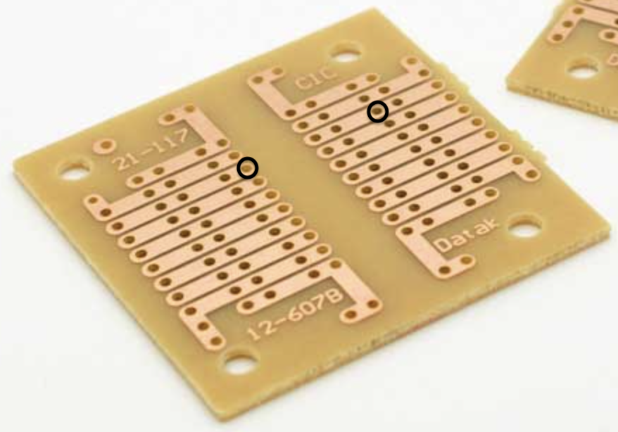 1.2. With the numbers 21-117 at the top, solder a short wire into the holes marked to the right connecting them
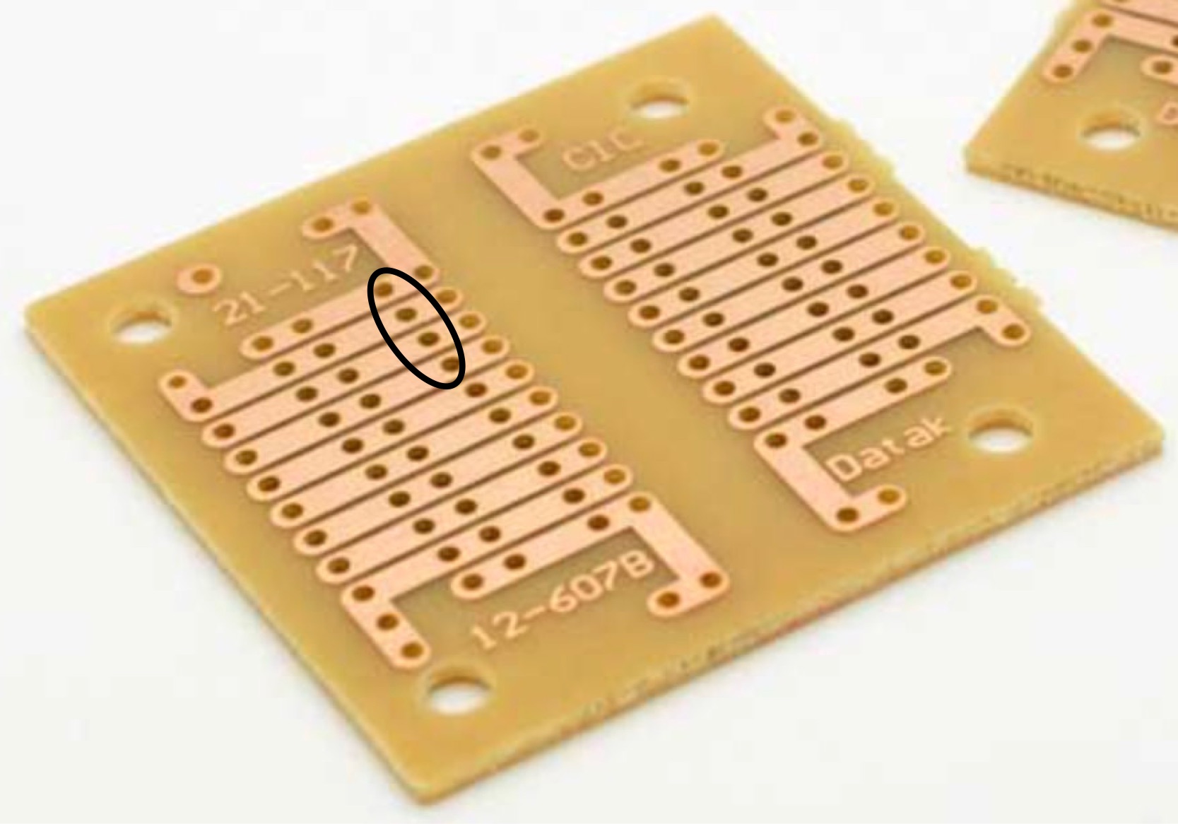 1.3. To mount the LMV358, solder a pin header of 4 pins to the DATAK 12-607 in the location circled to the right so it forms a vertical line
1.4. Solder the LMV358 to the pin header, so that the LMV358 covers the short wire you soldered in step 2 above
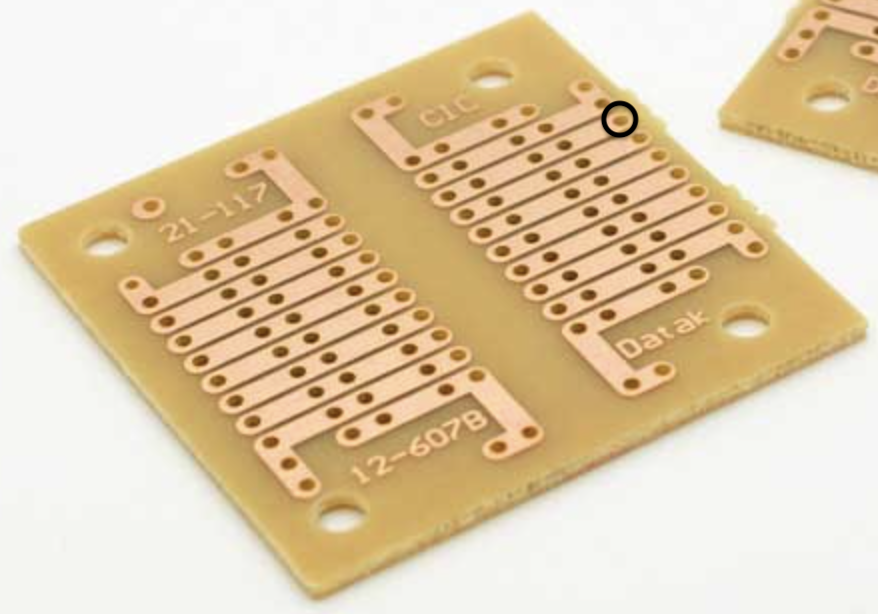 1.5. Solder a wire into the hole marked to the right, it should correspond to "Out" on the LMV358, but leave the other end alone (it will be soldered to the BNC Chassis)
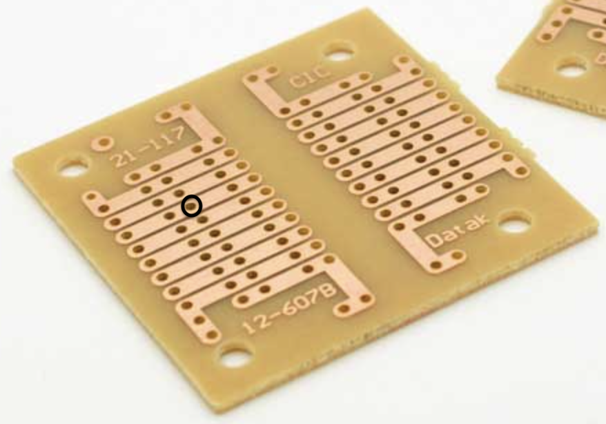 1.6. Solder a wire into the hole marked to the right, it should correspond to "In" on the LMV358, but leave the other end alone (it will be soldered to the MONO Jack)
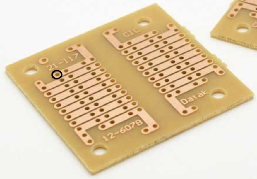 1.7.Solder a red wire into the hole marked to the right, it should correspond to "VCC" on the LMV358, but leave the the end alone (it will be soldered to the Power Jack)
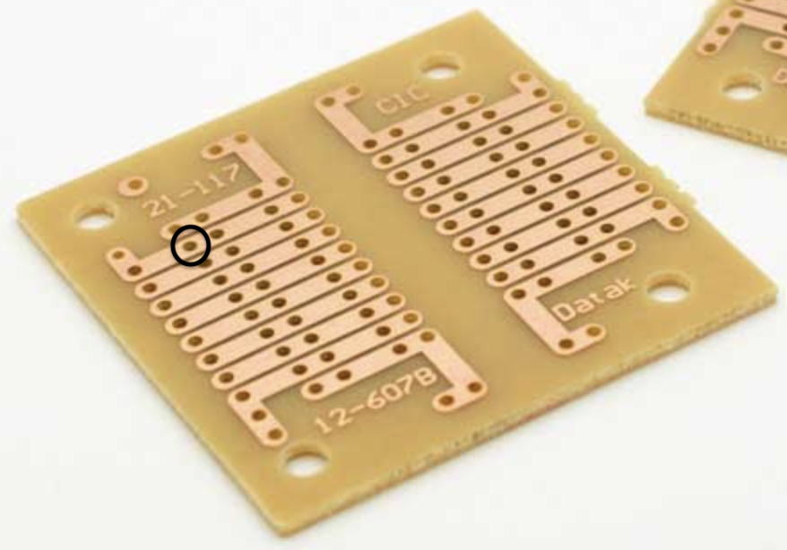 1.8. Solder a black wire into the hole marked to the right, it should correspond to "GND" on the LMV358, but leave the the end alone (it will be soldered to the Power Jack)
-
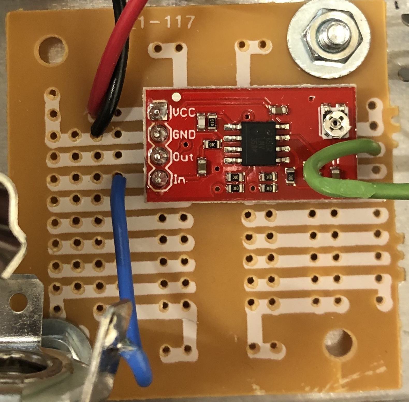
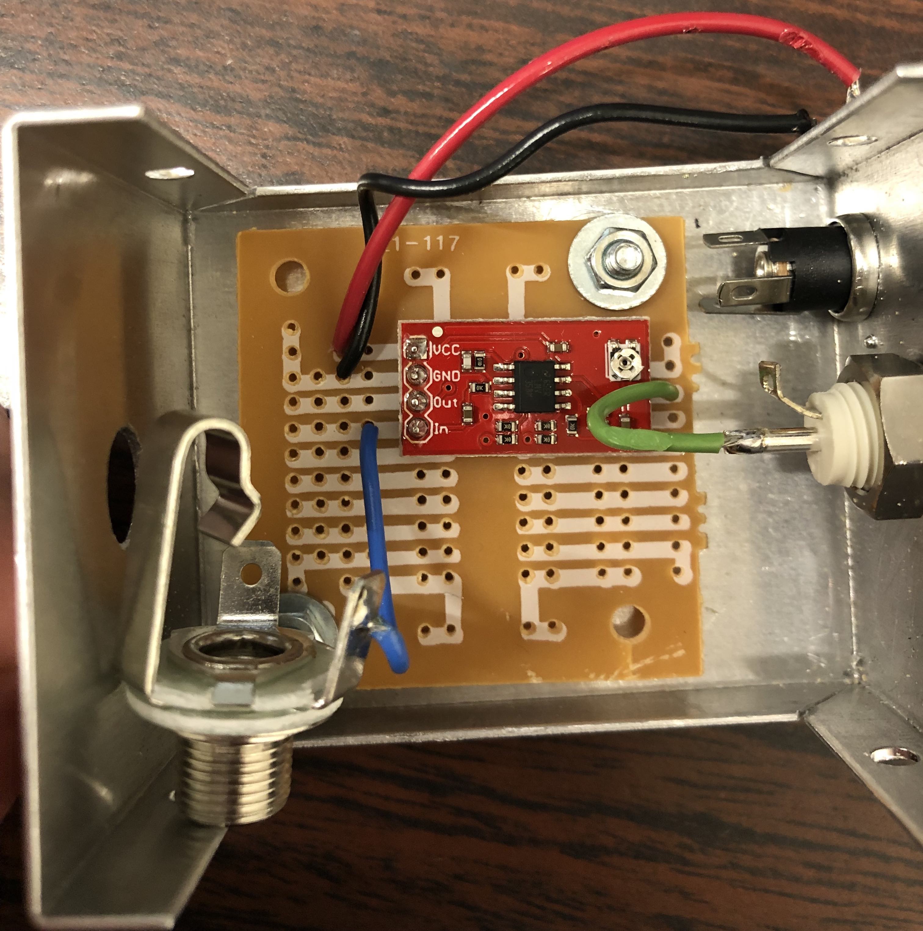
- Final Board
- Final Board
-
-
Clip the bottoms of the pin header to ensure that the circuit does not short by touching the metal container
-
Drill Holes
- BNC Chassis: 3/8" bit
- Power Jack: 0.3185" (8-8.5mm) bit
- 1/4" Phono Jack: 0.375" (3/8) bit
- 6-32 Screws: 0.1495" bit
-
Drill Hole Locations
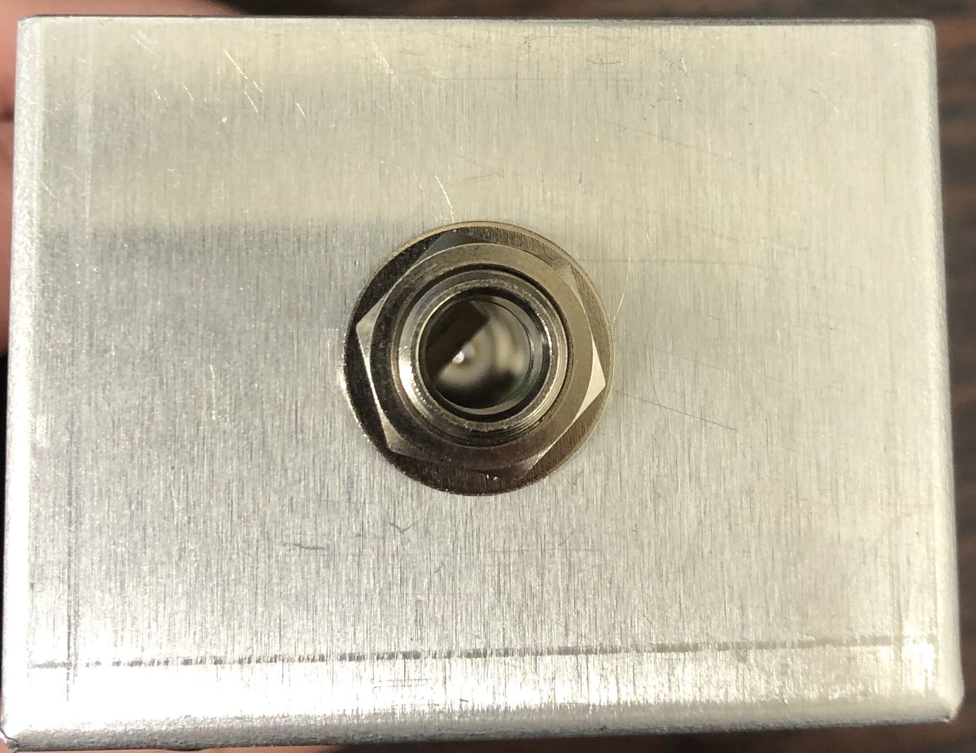 4.1. BNC Chassis and Phono Jack: center of smaller sides (to the right is an example of the side with the Phono Jack)
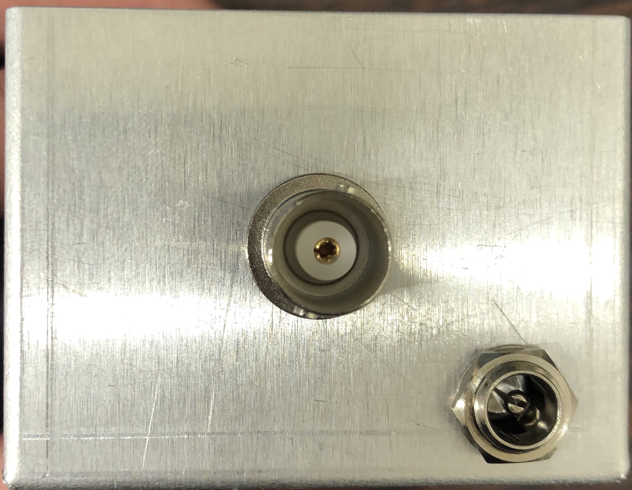 4.2. Power Jack: 0.5" on diagonal from corner
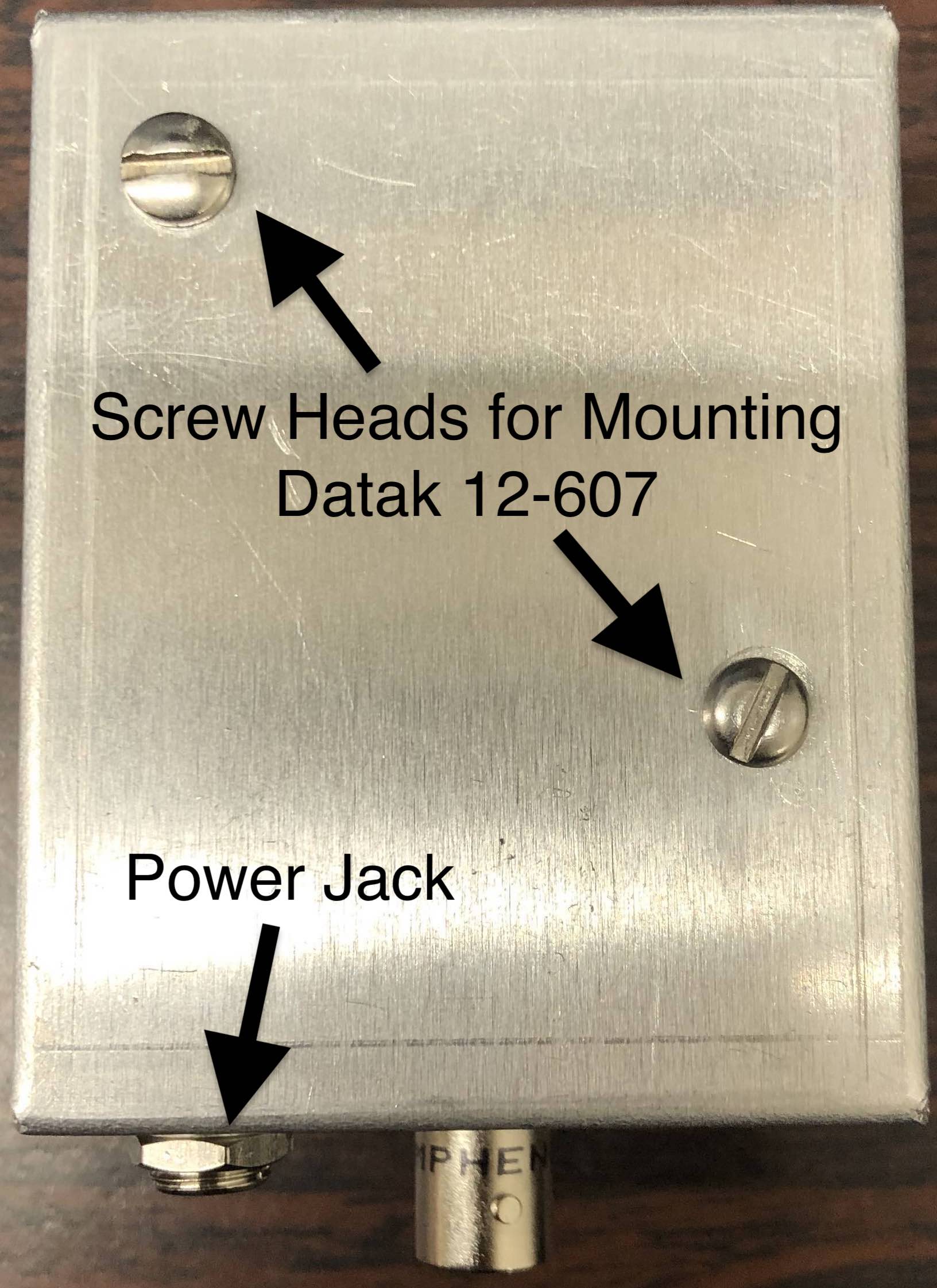 4.3. Trace out 2 6-32 screw holes on the solid bottom of the box using DATAK 12-607 as a guide; they should be closer to the side without the Power Jack
 -
Use a file to remove any remaining pieces of metal and to clean up the holes you just drilled
-
Mount the DATAK 12-607 to the box using the 2 6-32 screws, the 4 #6 washers, and the 4 6-32 nuts
6.1. Insert a screw into each of the holes and secure it with a nut
6.2. Place a washer on top of the nut and then slide the DATAK 12-607 into place over the screws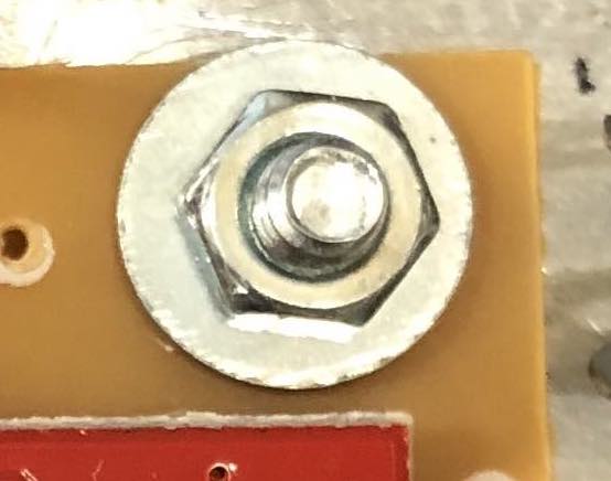 6.3. Place another washer on the screw over the DATAK 12-607 and then secure it with a nut
 -
Attach the Power Jack to the hole that is 0.5" from the corner
-
Attach the BNC Chassis to the middle hole on the same side as the Power Jack
-
Attach the MONO Jack to the middle hole on the opposite side as the Power Jack and the BNC Chassis
-
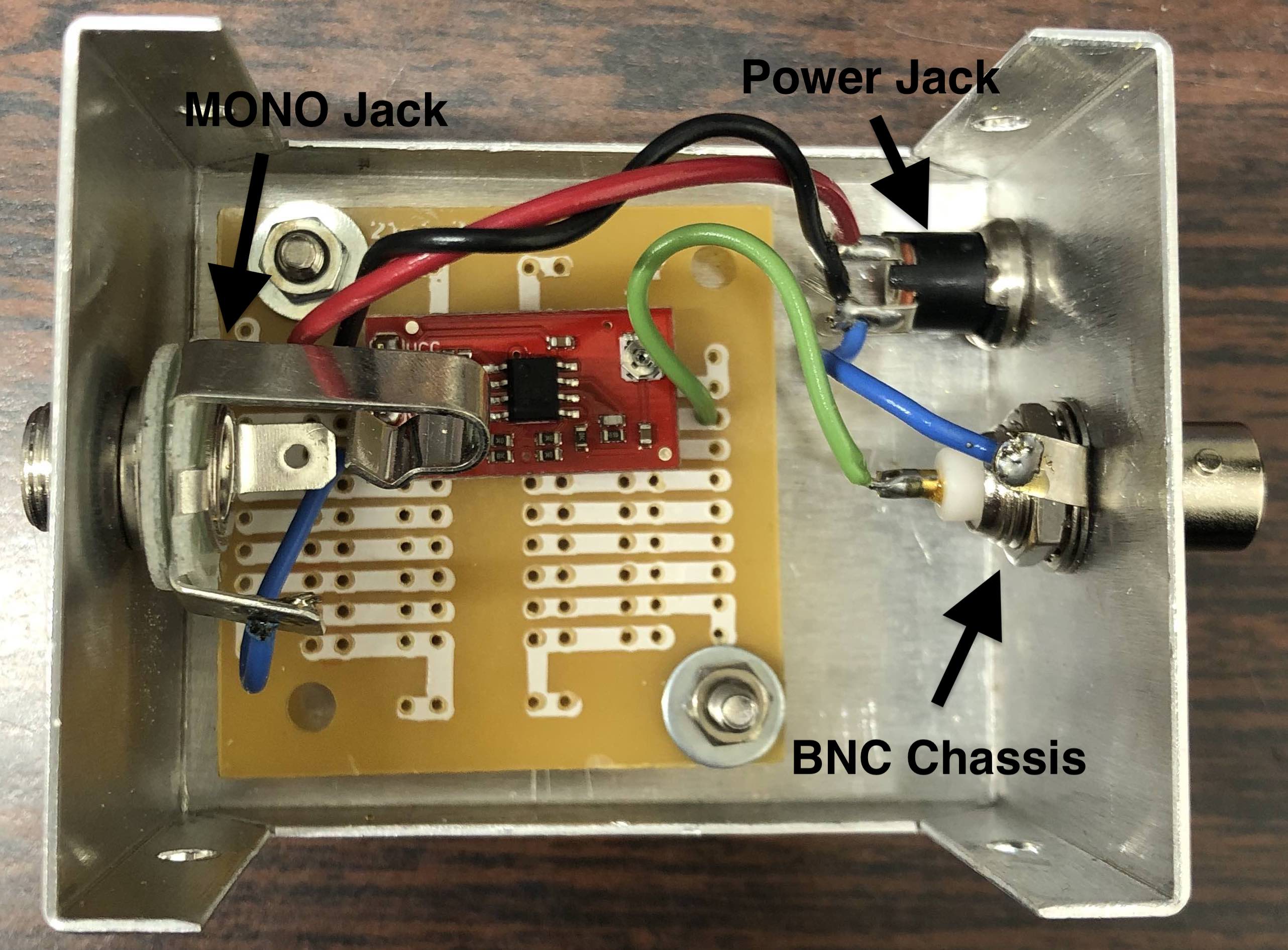
Solder remaining wires in place (see above photo). Be sure to add a short wire connecting the BNC Chassis to ground (blue wire on right side of photo above).
-
Rotate the trimpot counterclockwise until it can no longer rotate then test the preamp to ensure it is working correctly.
-
Place the four rubber feet onto the bottom corners of the preamp.
-
Label the preamp with the following labels:
a. "Microphone Pre-Amp" on top (side DATAk 12-607 it attached to)
b. "Mic Input" above Mono Jack
c. "+5 VDC" next to Power Jack
d. "Output to Scope" beneath BNC Chassis