¶ Sound-Controlled LED Circuit Documentation
¶ Schematic
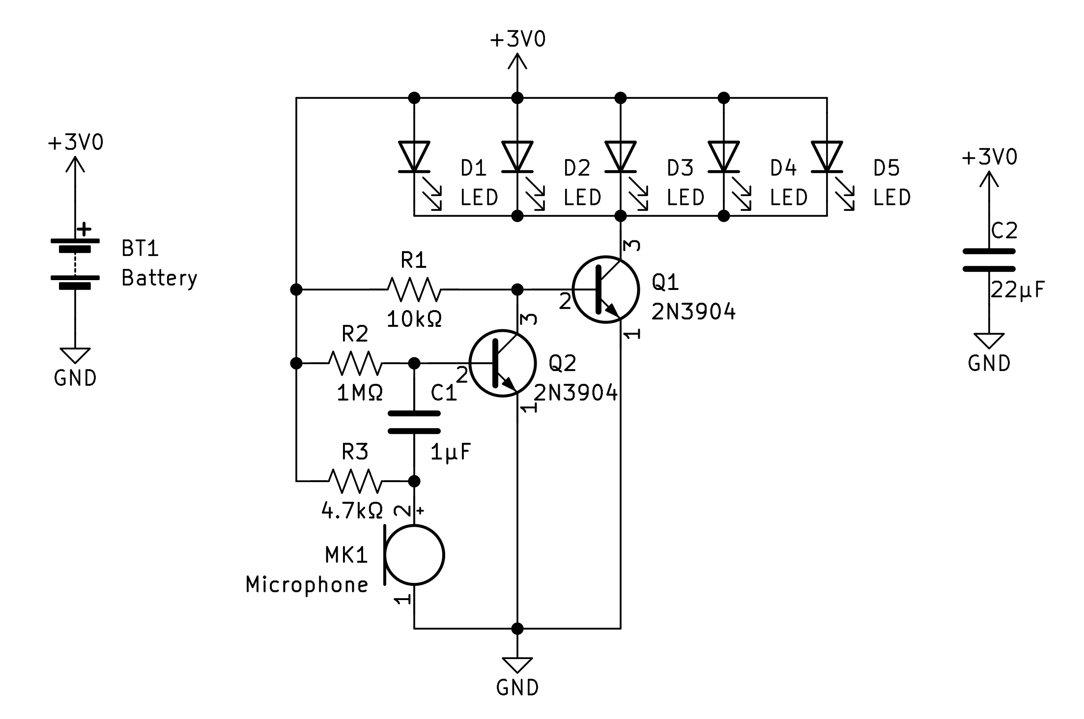
¶ Circuit Description
A small portable LED circuit that lights up in response to sound. The circuit operates on a 3V CR2032 coin cell battery attached to a microphone. When sound hits the microphone, it emits an electrical signal which is coupled by a capacitor to the first transistor for amplification. This amplified signal is sent to the base of the second transistor which drives the LEDs to emit light. The louder the sound, the brighter the LEDs. Additionally, the five LEDs in the circuit come in five different colors at evenly spaced wavelengths within the visible spectrum.
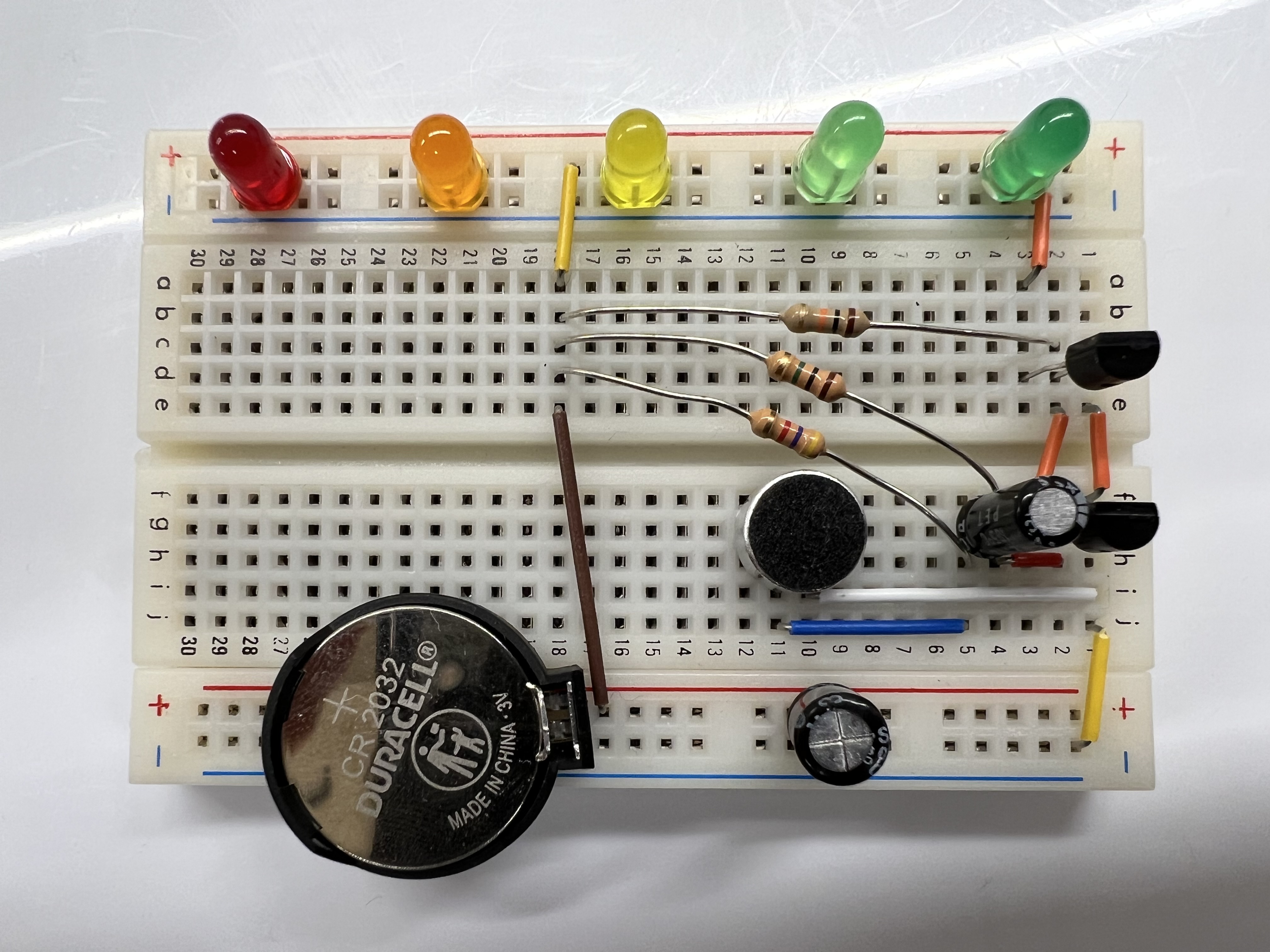
¶ Breadboarded Circuit
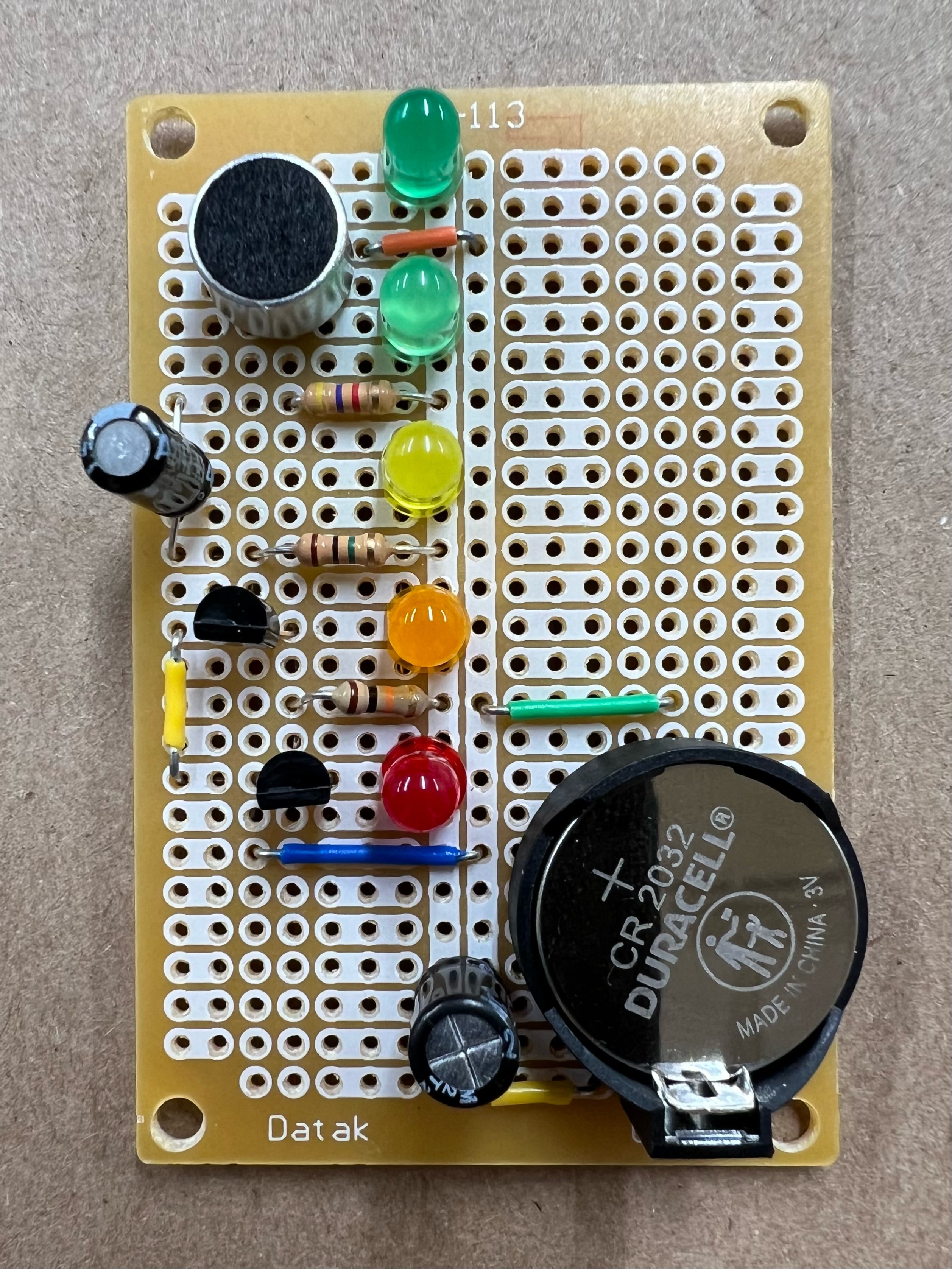
¶ Soldered Circuit – Version A
¶ Assembling the Circuit – Version B
If you're new to soldering, check out the Soldering Guide.
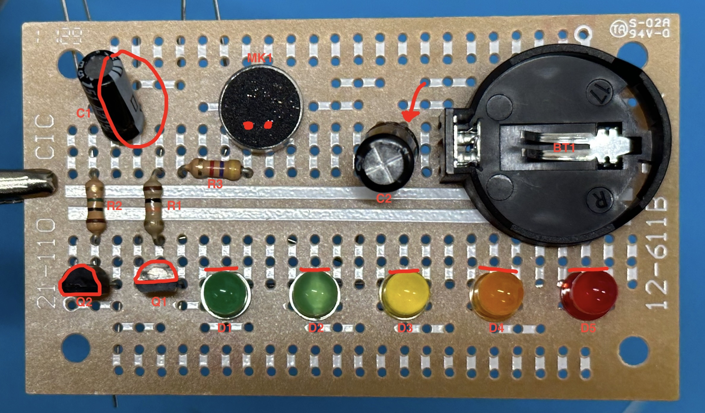
First, insert the components into the PCB like shown in the image below. The reference designators (R1, for example) are labeled to match the schematic.
Pay close attention to the following:
- The polarity of C1. Make sure the negative stripe is on the correct side (this is circled in the image).
- The microphone. This has polarity as well, so you need to insert it in the correct orientation. The pins are not at the center of the microphone, so if you insert it as shown in the image (the red dots indicate the pins underneath), you should be fine.
- The polarity of C2. This capacitor may lack a negative stripe. If this stripe is indeed missing, orient the capacitor so that the longer pin goes into the hole that the red arrow points to in the image.
- The orientation of transistors Q1 and Q2. As shown in the image, the flat sides of the transistors must face away from the center of the PCB.
- The polarity of the LEDs. Look closely at each LED – you will see that they are almost perfectly round, but one side will be flat. In the image, the red line next to each LED indicates the flat side. Make sure you insert the LEDs in the correct orientation.
- The orientation of the battery holder. This should be pretty self explanatory.
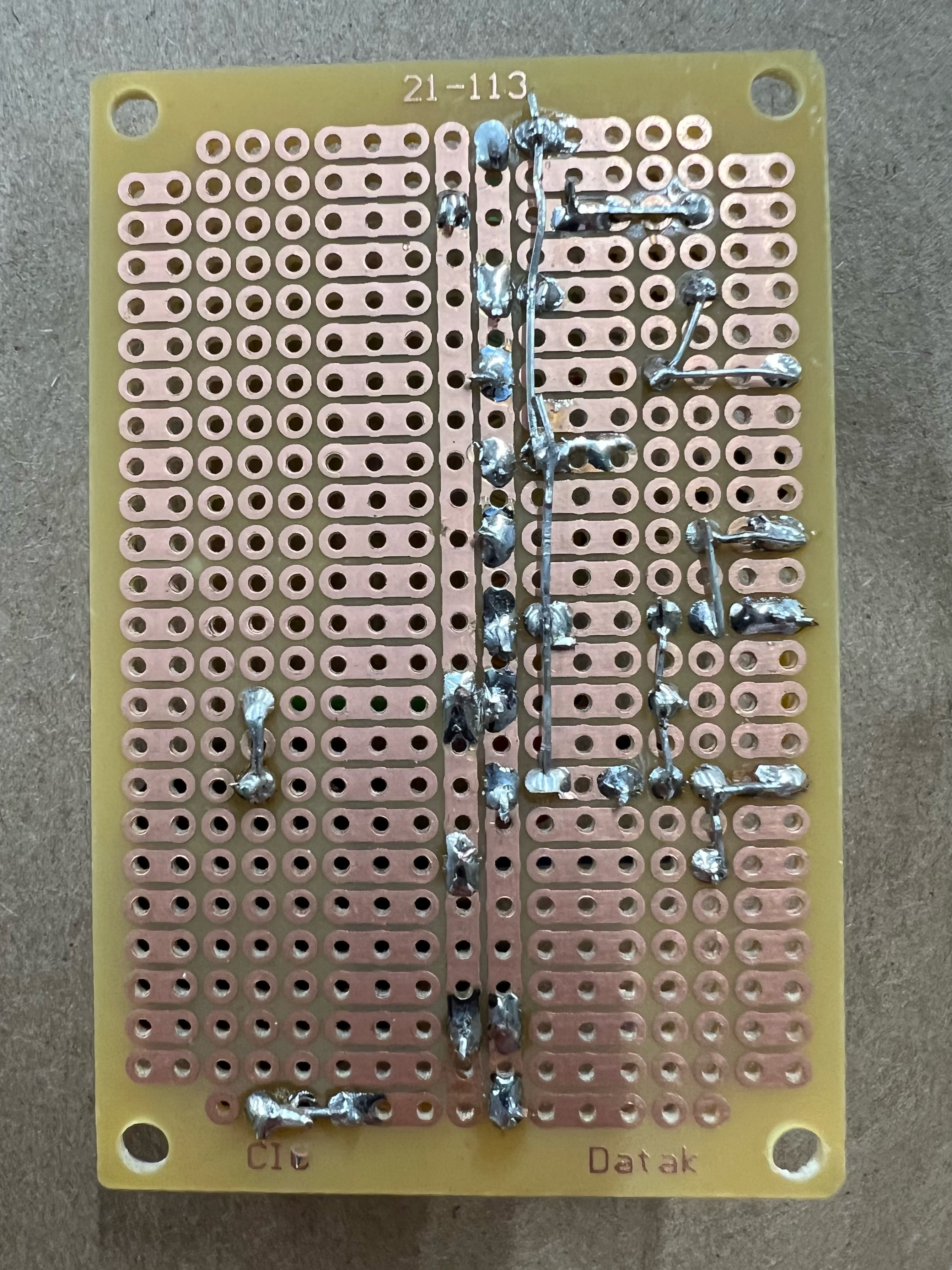
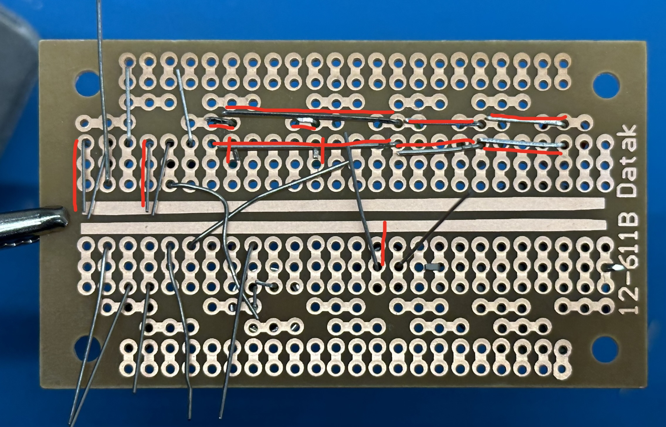
Next, bend the pins under the board as shown in the image below. The red lines indicate where certain pins should be bent. The pins that do not have a red line next to them can be bent in any desired direction. You may also need to trim some of the pins so they are not too long.
Note that the image below is as if the board in the image above were flipped over "hamburger style". That is, the LEDs are at the top in the image below rather than at the bottom in the image above (and the transistors remain on the left side).
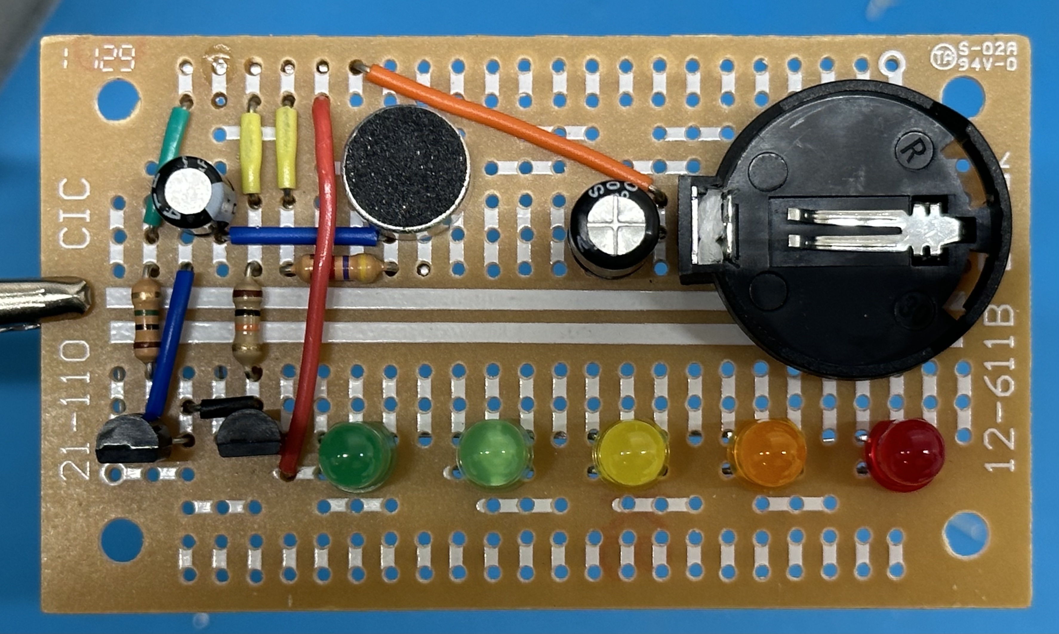
After bending the pins, insert jumper wires as shown in the image below. Be sure to insert them in the correct holes. There are eight total jumpers to be inserted (note the black one just above Q1).
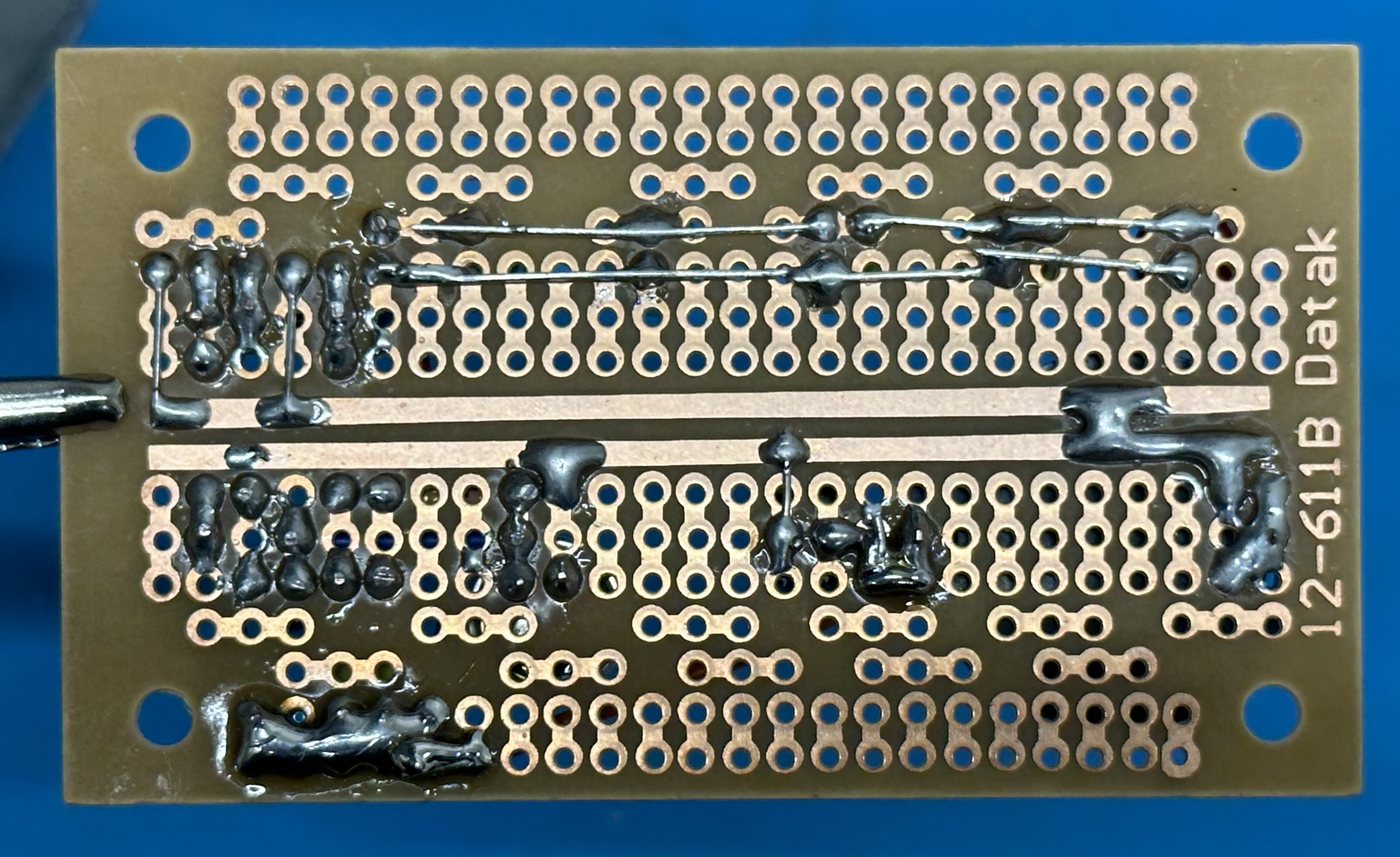
Finally, solder the bottom of the board according to the image below and trim all the pins. Pay close attention to the solder bridges. These are required for the board to function, and being able to create neat solder bridges is an important skill.
¶ Component List
- Red LED: datasheet_led_red.pdf
- Orange LED: datasheet_led_orange.pdf
- Yellow LED: datasheet_led_yellow.pdf
- Yellow-Green LED: datasheet_led_yellow-green.pdf
- Green LED: datasheet_led_green.pdf
- Condenser Microphone: datasheet_microphone.pdf
- CR2032 Coin Cell Battery: datasheet_battery.pdf
- Battery Holder: datasheet_battery_holder.pdf
- 2N3904 Transistor: datasheet_transistor_2n3904.pdf
- 1µF Capacitor: datasheet_capacitor_1uf.pdf
- 22µF Capacitor: datasheet_capacitor_22uf.pdf
- 1MΩ Resistor: datasheet_resistor_1m.pdf
- 4.7kΩ Resistor: datasheet_resistor_4pt7k.pdf
- 10kΩ Resistor: datasheet_resistor_10k.pdf
- Breadboard or Printed Circuit Board
- Wire Jumpers