¶ Overview
¶ Storage
¶ Location
TBD
¶ Special Storage Instructions
TBD
¶ Equipment Management
¶ Initial Construction
¶ 3-D Printed Parts
| Part | Picture | Infill | Shells | Brim | Other |
|---|---|---|---|---|---|
| Idler | 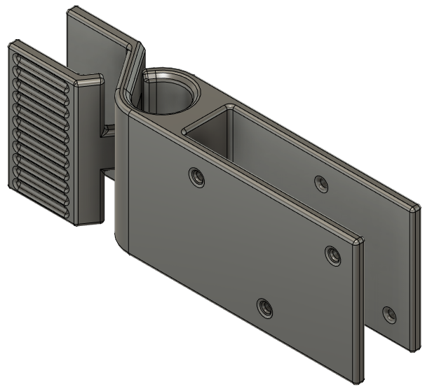 |
25% | 5 | 5 mm | - |
| Guide | 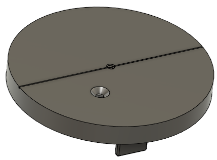 |
15% | 3 | none | - |
| Table Clamp (2) | 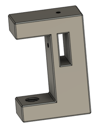 |
50% | 5 | none | - |
| Table Clamp Fastener (2) | 15% | 3 | 5 mm | Reduce scaling in x- and y- directions to 97% | |
| Table Clamp Fastener Cap (2) | 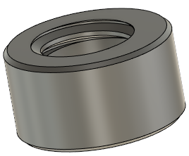 |
15% | 3 | 5 mm | - |
¶ Other Parts
- 33.5 in X 9.5 in large wood plank
- 9.5 in X 2.75 in smaller wood piece
- Piano hinge
- 13 #4 X 3/4 wood screws
- 4 #8-32 X 1/4 set screws
- 1 #4-40 X 1/4 binder screw
¶ Construction Steps
- Set up prints for any needed parts. Adjust infill, number of shells and brim according to the table above.
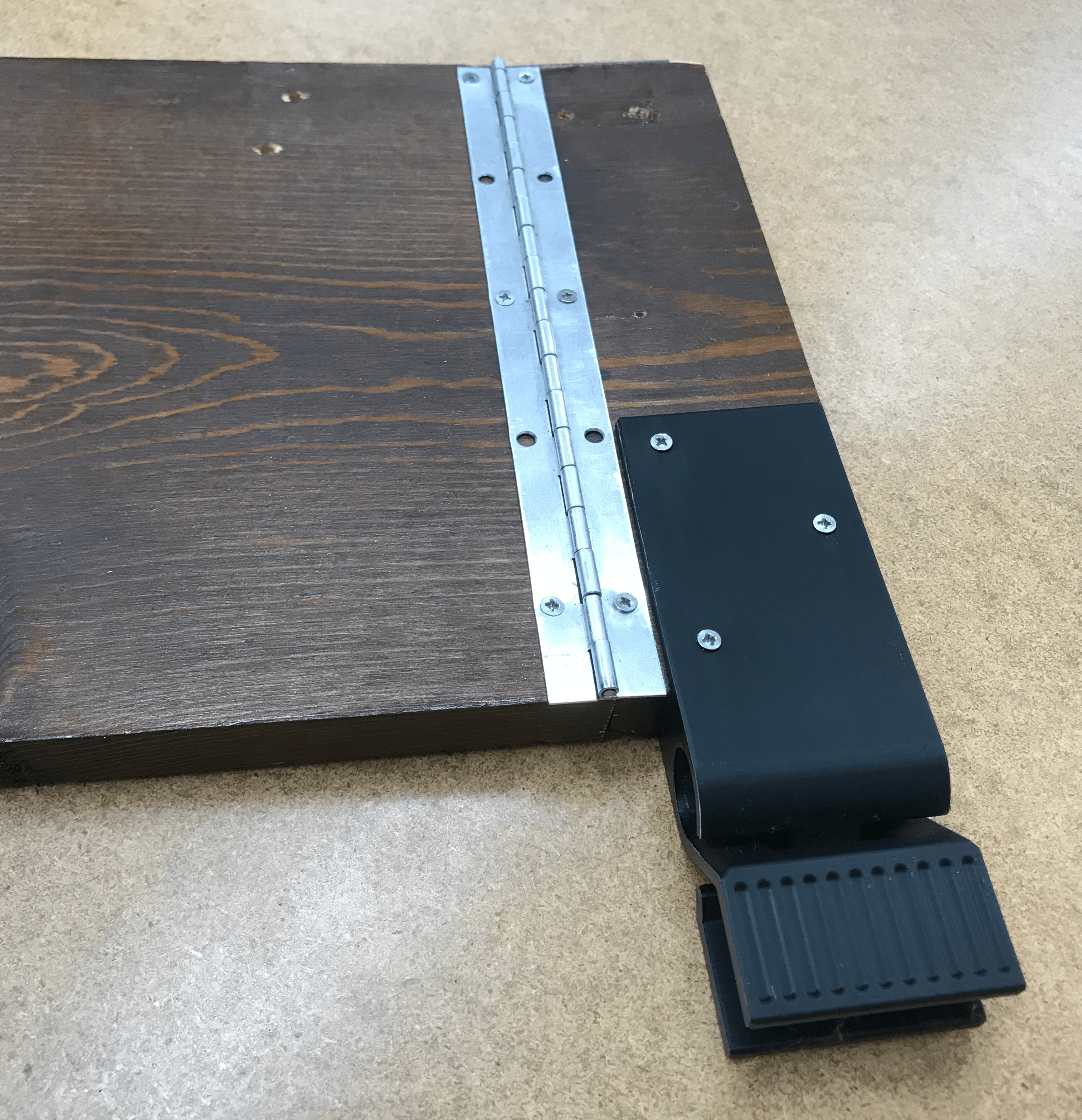
- Take the hinge and small wood piece to Lewis to have the hinge cut down to size (about 9.25 in). Cut both ends of the hinge so that the holes are centered. Fasten the hinge to the wood plank and smaller wood piece with 6 wood screws (ensure the hinge is at the very edge of both wood pieces)
- Fasten the idler to the smaller wood piece, just above the hinge, using 6 wood screws.
- Use the #4-40 tap on the center hole of the guide, and the #8-32 tap on the 2 set screw holes on each of the table clamps.
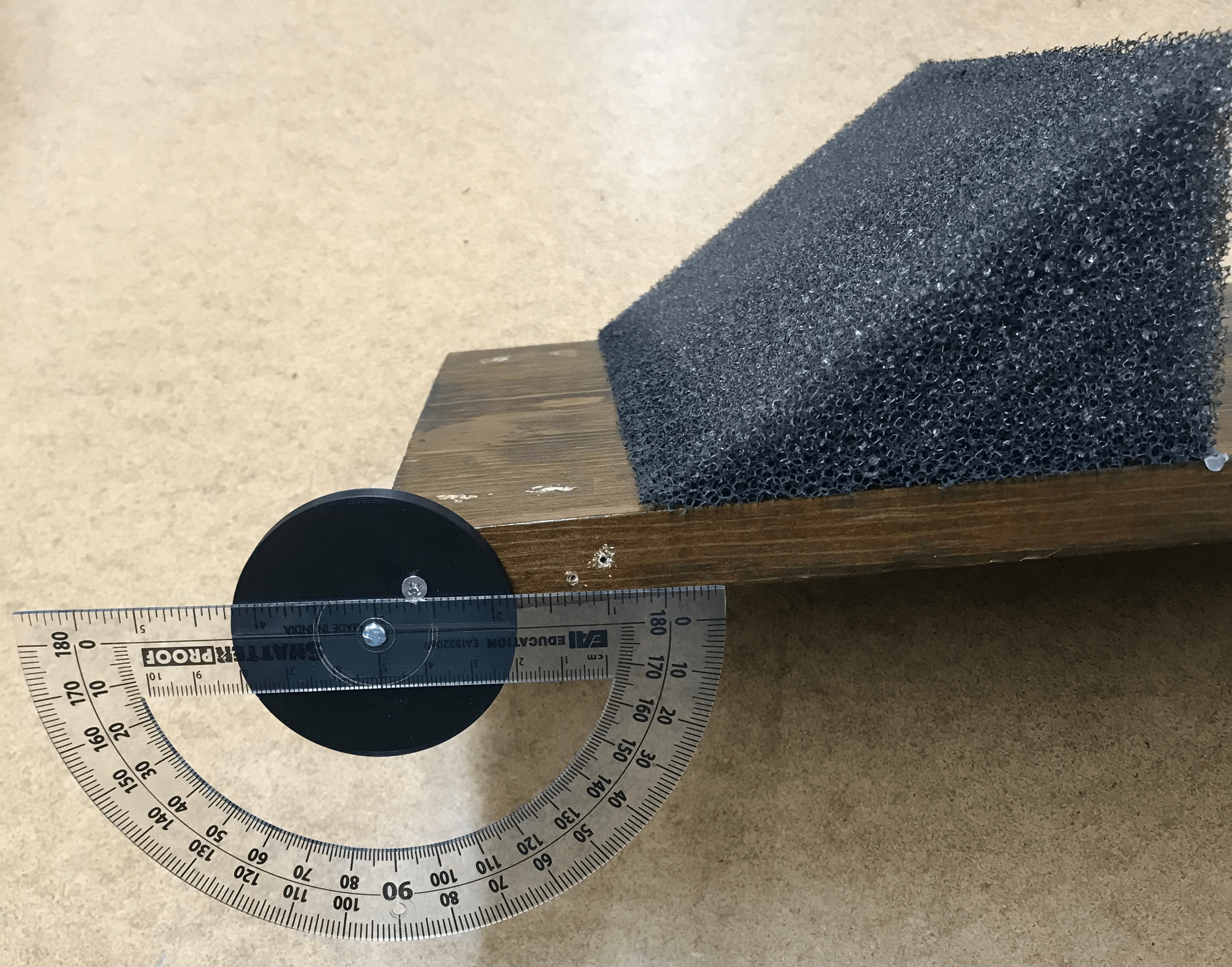
- Attach the protractor to the guide using the binder screw. Line up the 0°/180° line on the protractor with the line on the guide before tightening.
- Attach the guide to the lower end of the large wood plank. If the lower end is on the left, the square guide should sit on the top-left corner of the plank. Fasten the guide in place with 1 wood screw.
- Use an allen key to turn 2 set screws into each of the table clamps. These will be used to hold the meter stick in place.
- Turn the table clamp fastener through the bottom hole in the table clamp. Screw the fastener cap on. The cap should twist on like a lid and after a certain point, it should rotate freely on top of the fastener body.
¶ Maintenance
TBA
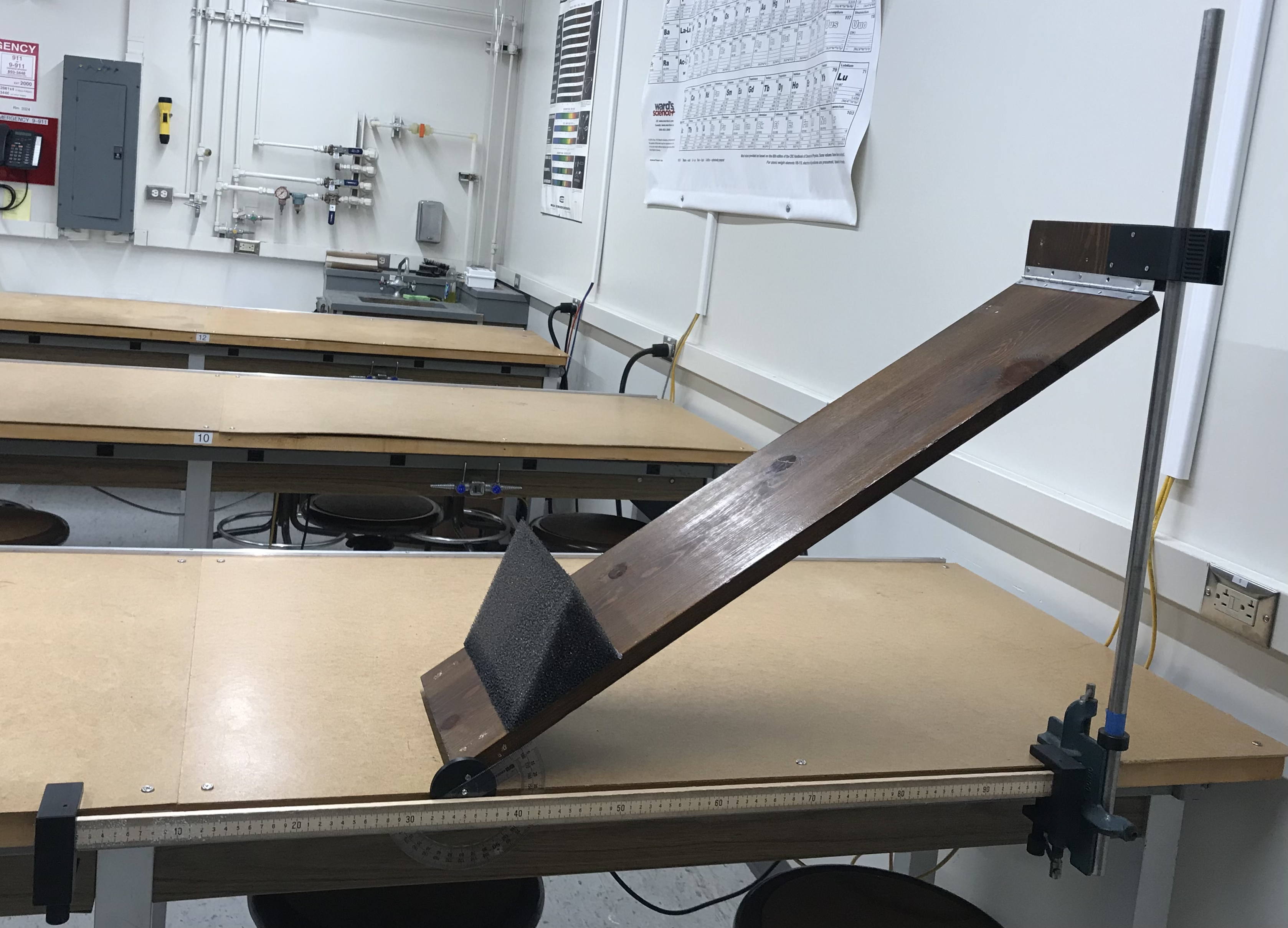
¶ Lab Set-Up
¶ Additional Lab Supplies Needed
- Meter stick
- Large table clamp with 3/4" rod
¶ Set-Up Steps
- Mount the large table clamp with 3/4” rod to the right side of the lab table. Use the cheat bar to tighten the table clamp.
- Slide the idler (attached to wood assembly) onto the rod.
- Turn wood assembly so that the guide is resting along the side of the lab table.
- Attach the 3D-printed table clamps to the ends of the meter stick. Use an allen key to tighten the set screws so the meter stick is fixed. Mount the meter stick/table clamps assembly and position such that the inclined plane can still move to its maximum and minimum angles.