¶ Catch Box
¶ Location
¶ Storage
¶ Maintence
¶ How It's Made
¶ Materials
- Acrylic Box (A, 10oz, 5½” 3⅛” 1⅛”)
- Styrofoam (12 Pack of 6”x6”x1” EPS Polystyrene Cubes)
- Foam (Tear-Resistant Super-Cushioning EVA Foam Sheet, ¼” thick)
- Scissors
- Styrofoam Cutter
- ¾” Bar with Table Clamp
- ½” Bars (x2)
- Right Angle Clamps (x4)
- ¼ 20 Screws (2” long) (x2)
- ¼ 20 Flange Nuts (x4)
- ¼ 20 Nuts (x4)
- Test Leads (Minigrabber to Banana) (x2)
- 15” Piece of Stainless Steel Wire
- Power Supply
¶ Instructions to Build Styrofoam Cutter
- Attach the ¾” bar to the table using the table clamp. Attach the two ½” bars to the ¾” bar using two of the right angle clamps. Space the two ½” bars about 10” apart.
¶ ½” Bars on ¾” Bar
2. Attach the two remaining right angle clamps to the ends of the ½” bars (see photo above).
3. Put two flange nuts on each screw so that the flange sides are facing each other. Then, put two of the regular nuts at the end of the screw and tighten them against each other to lock them in place.
4. Wrap blue tape around the nuts at the end of one of the screws to insulate it from the bar setup.
¶ Nuts with Tape
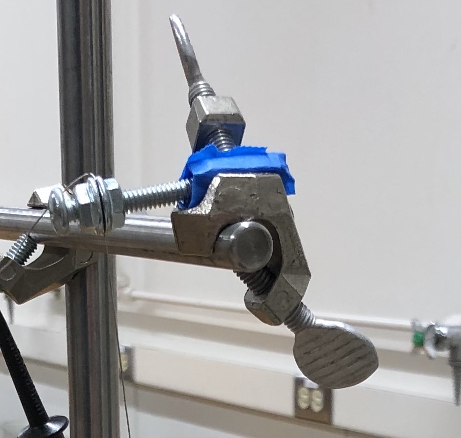
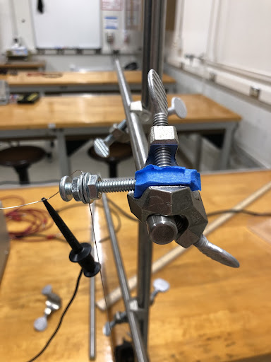
5. Place the ¼ 20 screw into the right angle clamp at the end of the ½” bar so that the nuts tighten against each other are what the screw on the right angle clamp is tightened against (this is done so that the threads on the screw are not damaged by the right angle clamp).
¶ Screw from Right Angle Clamp Tightened onto Nuts
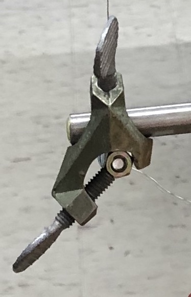
6. Wind the wire around one screw a few times between the two flanged nuts. Tighten the flange nuts to help hold the wire around the screw. Repeat this on the second screw, but make sure that the wire is taut between the two screws. You may need to adjust the right angle clamps to keep the wire taut.
¶ Wire Wrapped Around Screw with Flange Nuts
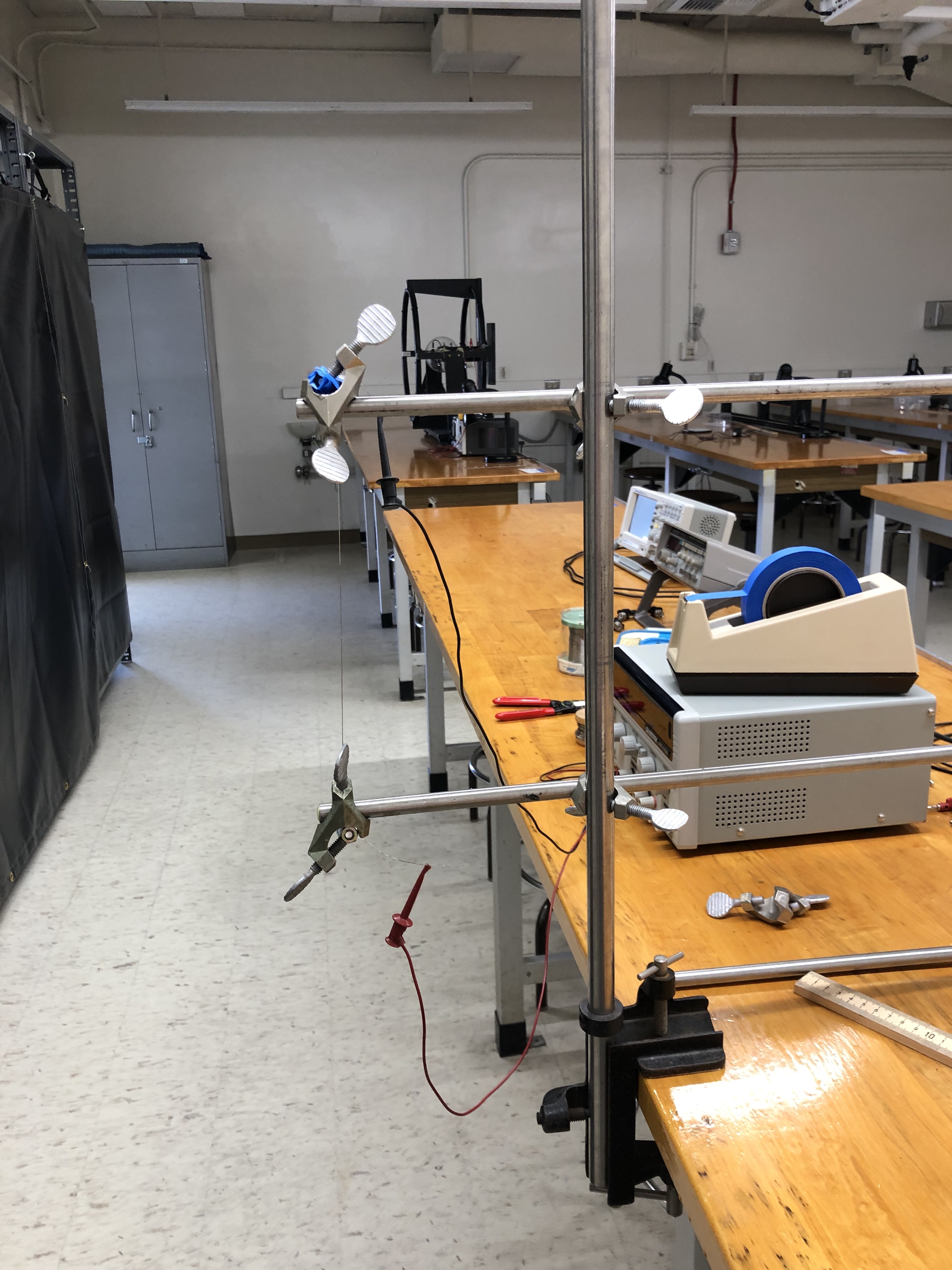
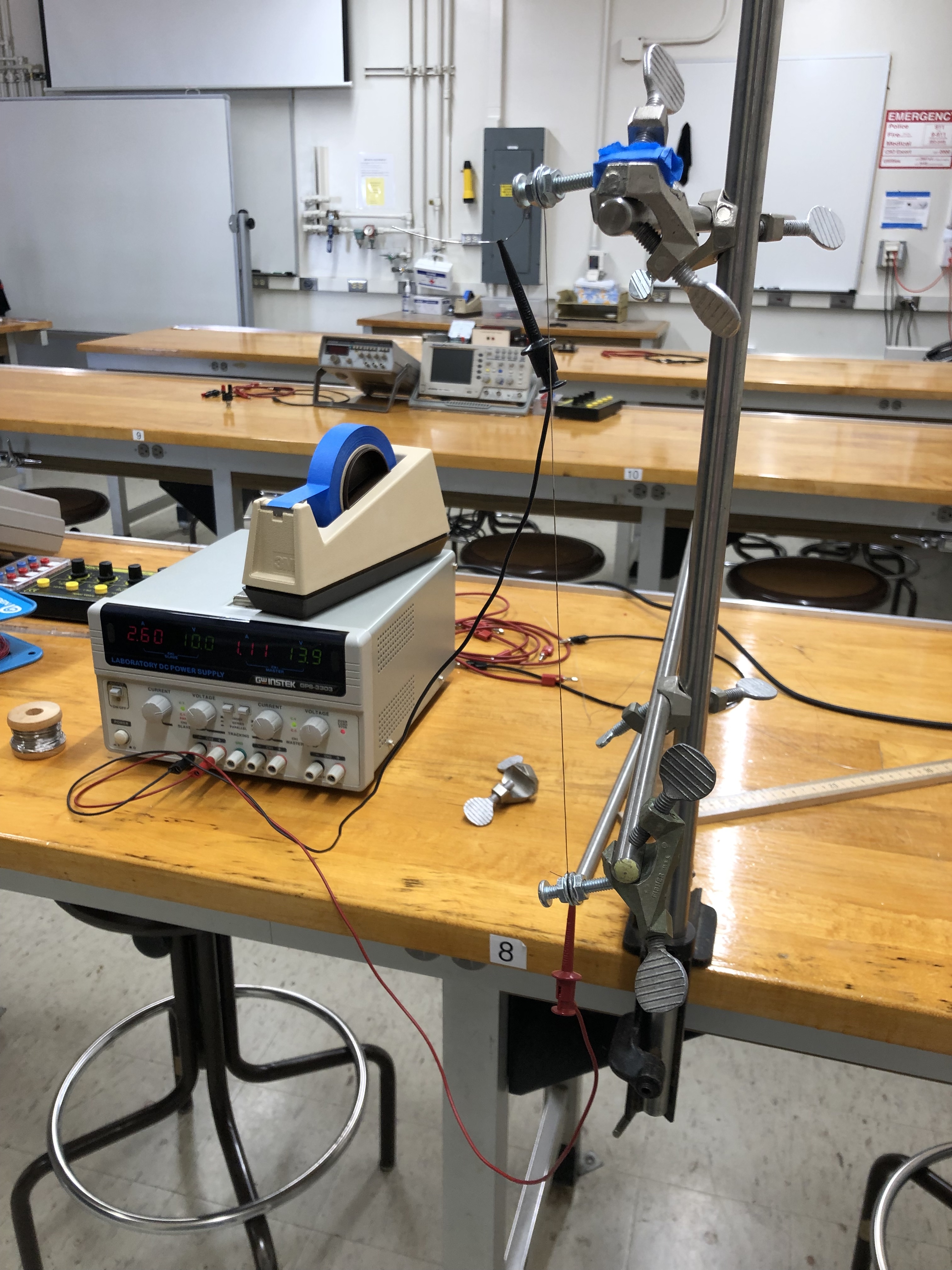
7. Plug the two test leads into the power supply and hook the minigrabbers onto the ends of the wire.
¶ Final Styrofoam Cutter Setup
¶ Cutting the Styrofoam
- Trace the outline of the acrylic box onto a styrofoam cube.
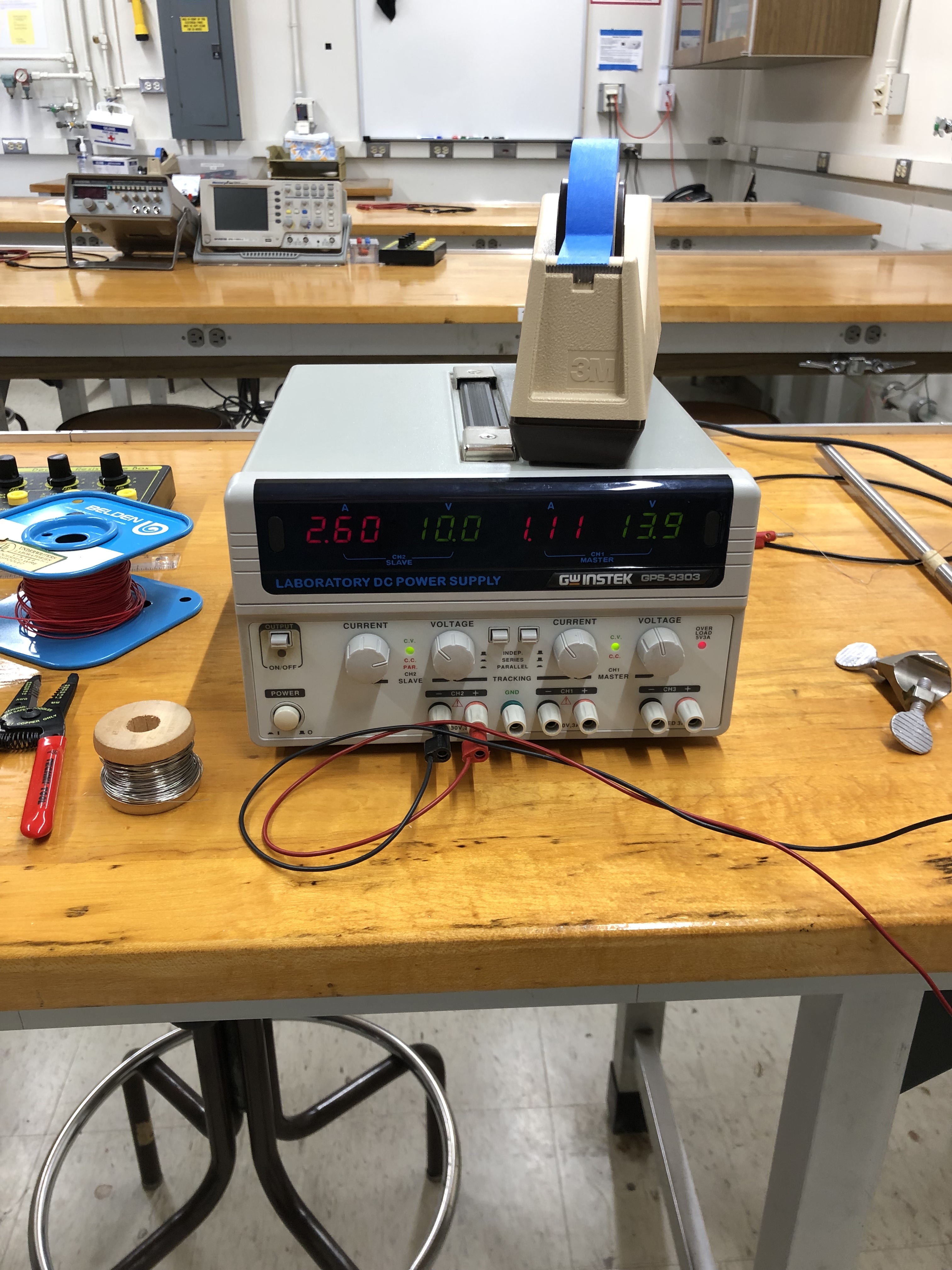
- To cut the styrofoam, turn the power supply on and wait a few seconds to allow the wire to heat up. You should see a decent change in voltage measured by the power supply. With the stainless steel wire used above, the measured voltage was about 6.7V.
¶ Change in Voltage Measured by Power Supply
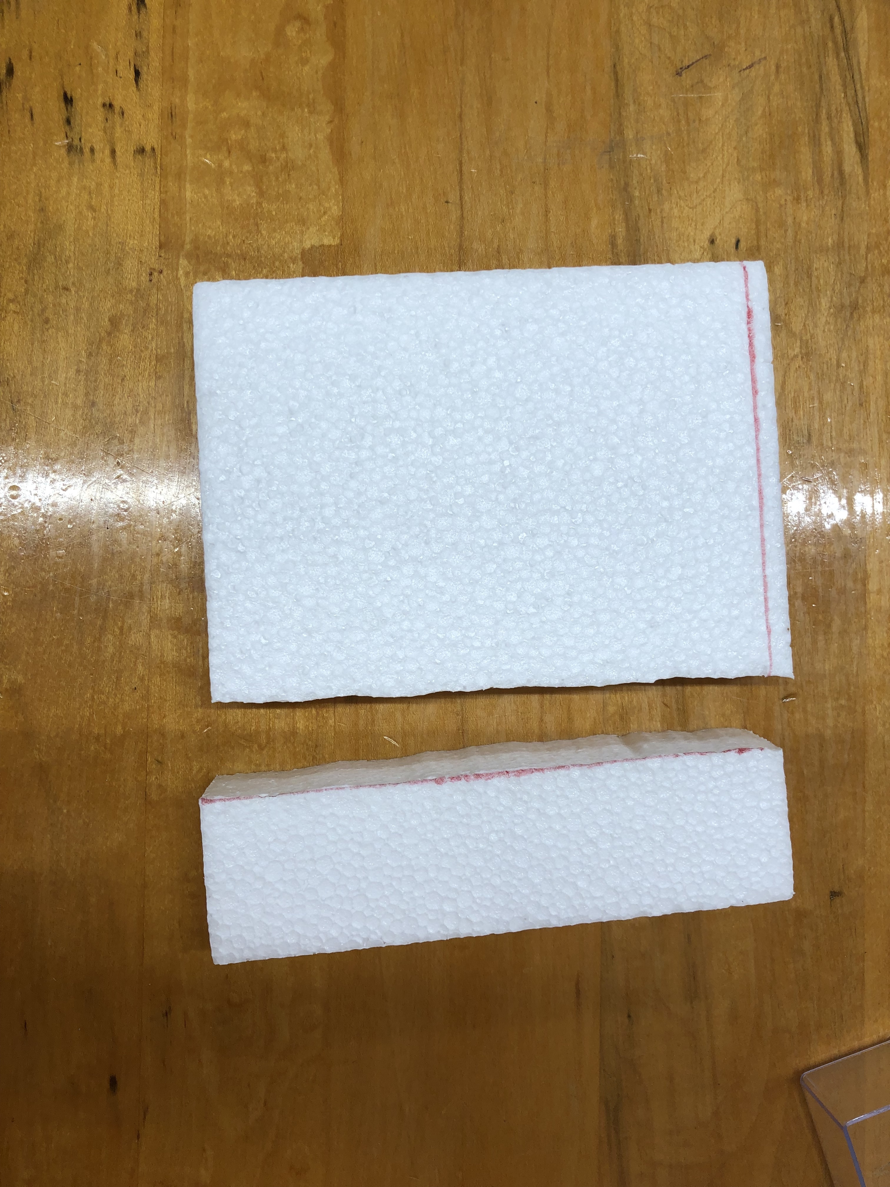
3. Do the cutting in a well ventilated area. Carefully hold the styrofoam and pull or push it across the wire to cut out the outlined shape.
¶ Cut Styrofoam
4. It is helpful to check that the styrofoam fits inside the acrylic box when finished cutting the outline because you may need to cut it more to get it to fit inside the box. It should be a snug fit.
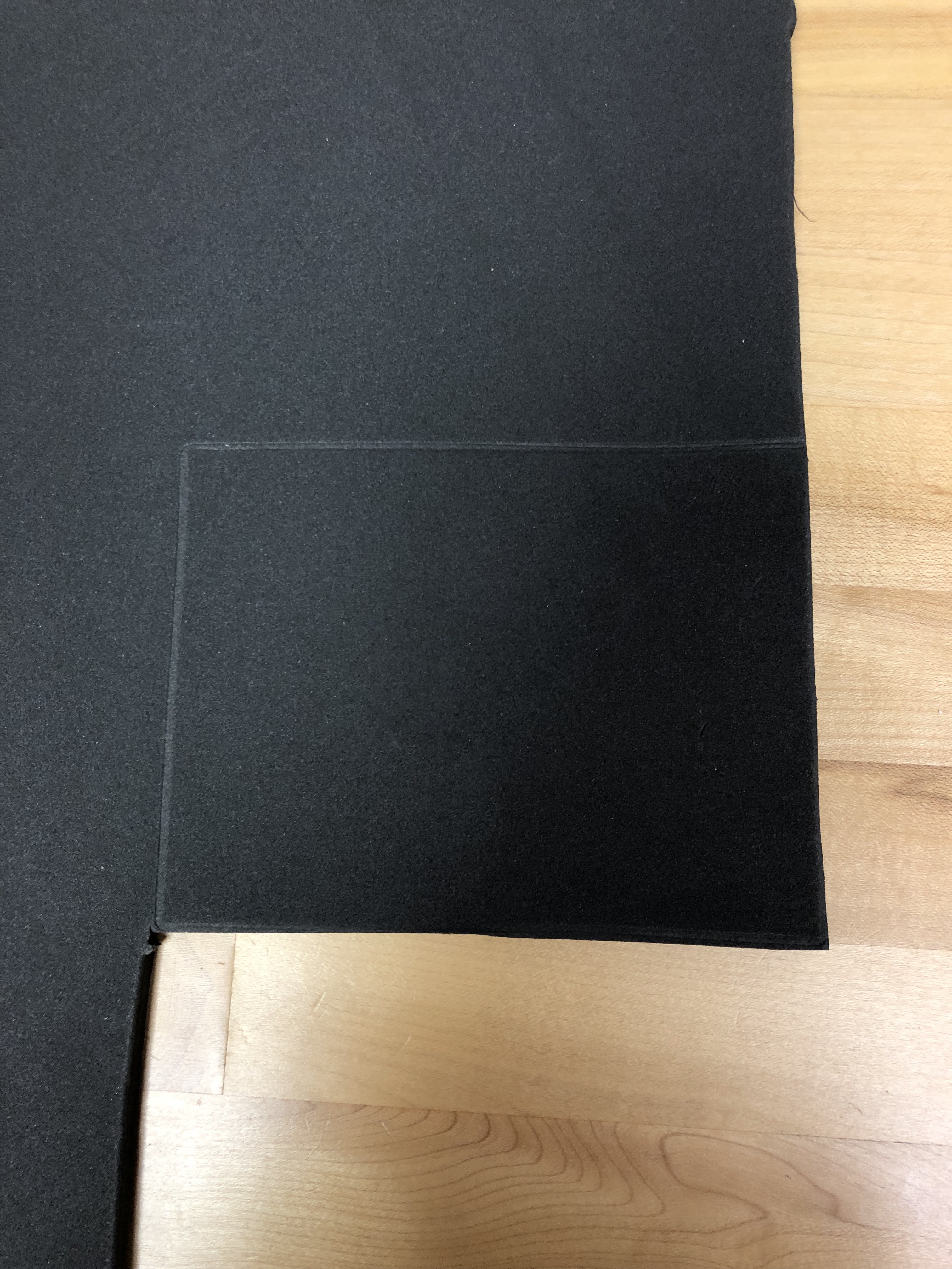
5. To cut the foam, it is helpful to place the acrylic box on it with the open side down and push down on the box, so that it leaves an imprint on the foam and you can cut it out using scissors.
¶ Imprint Left by Acrylic Box
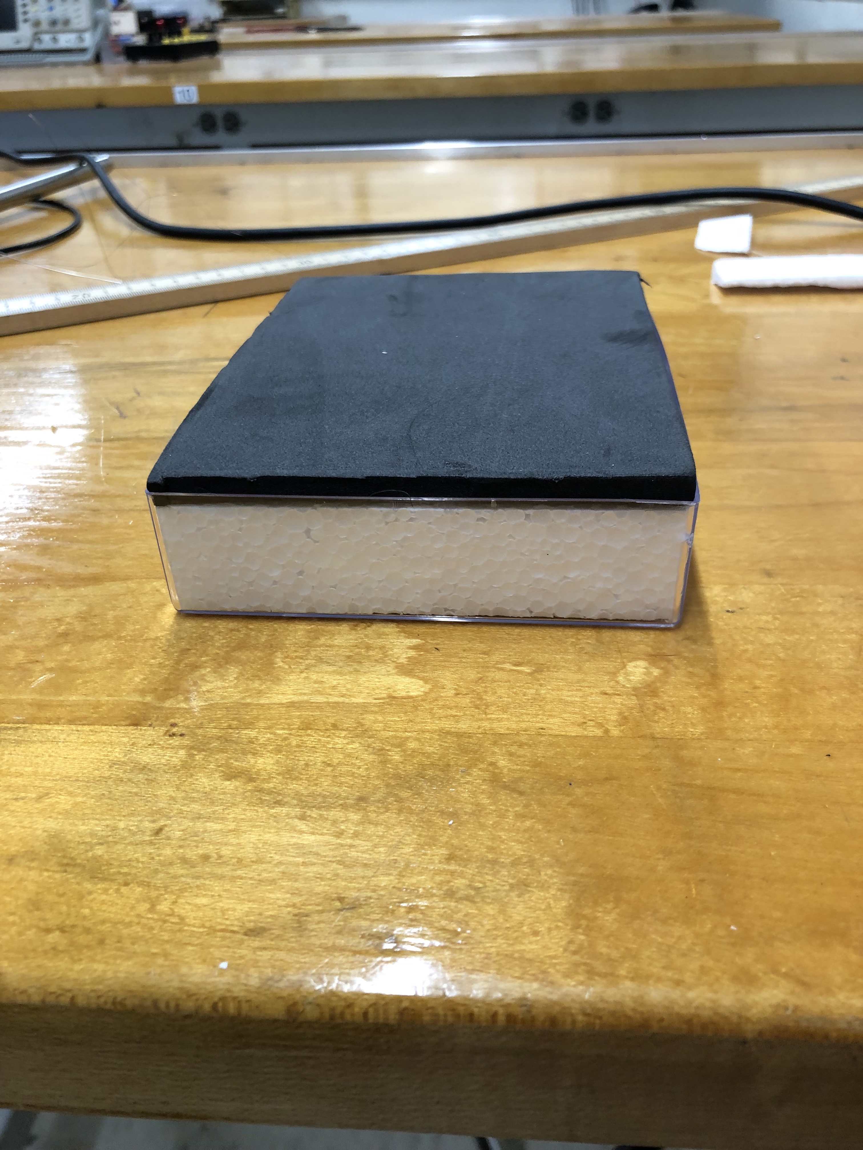
6. To assemble the catch box, first place the styrofoam in the acrylic box and then place the foam on top of the styrofoam.
¶ Catch Box Fully Assembled